

For many of us in the ophthalmic lens business, a term frequently heard is Diopter. While it is commonly used, it has been my experience that many people are unclear about the proper meaning(s).
One reason for the confusion over the term Diopter is this same word is used to describe three distinct and significant features of an ophthalmic lens: power (as measured on a focimeter or lensometer), prism power, and surface curvature (steepness of the lens surfaces). It is this latter meaning that we shall deal with in this discussion, as it is this meaning which is perhaps the least understood.
The steepness of the front (convex) and back (concave) surfaces of an ophthalmic lens are the most important factors in providing a lens of a given power. In the ophthalmic industry, it is common to express surface steepness by stating that a lens curve is “X” Diopters (1.53).
Before elaborating on how and why the lens surface curvature is defined in this manner, let’s digress a moment to highlight other factors which affect the power of a lens:
Index of Refraction
• The lens material’s index of refraction (N). This value is defined as the ratio of the speed of light in a vacuum divided by the speed of light in the material being considered. Light travels at a speed of 186,000 miles per second in a vacuum and is slowed when traveling through any other medium. The speed of light in our most standard plastic lens products is 124,166 miles per second. Therefore, the index of refraction of this material (Standard Plastic) is 186,000/124,166 = 1.498.
Lens Thickness
• The thickness of the lens at the point of measurement (usually its center). For plus power lenses, center thicknesses can be significant and variable (for differing lens powers and diameters). Minus power lenses generally have a center thickness between 1.5 to 2.0 mm independent of the curves and diameters chosen.
Prism
• If the front and back curves are tipped or misaligned from one another, the lens has prism at this point. If this prism is large, it can have an effect on lens power as well.
Moving on to the subject at hand: how do we define surface curvature (steepness) of an ophthalmic lens surface? Let us first examine the construction of the simplest of curves, a spherical surface. Looking at Figure I, such a surface has a common radius of curvature. If one were to take a string and tie one end to a pencil and hold the other end to a fixed point, the arc drawn as shown would be a circular arc. While this arc is in two dimensions, if it were rotated 360 degrees it would be a spherical surface. In drawing the arc, it is assumed that the string was kept a common length during this process.
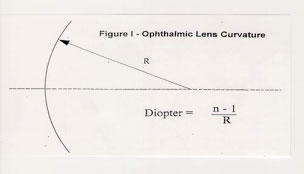
The radius of curvature of the arc would be the length of the string. If the string length were accurately specified in a known unit of measure, it would be clear to most as to how the surface would be reconstructed. For this illustration, let us use millimeters (mm) as the unit of measurement. The curve used in Figure I has a radius of curvature of 88.333mm.
If ophthalmic optics always utilized a commonly recognized unit of length (i.e., mm) to specify the surface curvature radius, there would be little chance of confusion as to its meaning. A radius value expressed in mm is universally understood (except for those who are still uncomfortable with the metric system).
For specifying surface curvature in ophthalmic optics, the term Diopter is utilized and defined by the following simple relationship:

Where “n” is replaced by an index value (more on this shortly) and R is the radius of curvature expressed in meters.
Ophthalmic lens surfaces are not easily visualized when dealing in mm radius values, and it is for this reason that the Diopter is especially useful. Utilizing Diopter curvature makes it more intuitive to approximate the second curve required to obtain a given lens power when fabricating a finished lens, for example, specifying curves of +6.00 (convex) and –4.00 (concave) permit one to estimate the power of that lens:
![]()
If the same lens curves were specified in direct units of length for our radius of curvature, it would not be apparent what the relationship would be:
![]()
Certainly I would not guess the Diopter (1.53) equivalent of the 4 curve would be 132.500mm, would you?
Notice the 1.53 shown in the parenthesis after the term Diopter. This standard nomenclature was introduced at the turn of the century and is now in common use in much of the world. For the United States, curvature is specified almost exclusively in this manner. Simply stated, for the purpose of specifying the lens surface, we pretend that the lens material has an index of refraction of 1.53. This value was close to the index of refraction of common glass used at that time. Therefore, to compute the Diopter (1.53) curvature of our surface of 88.333mm radius, we simply substitute the n and R values as follows:

Notice that we must divide the R (mm) value by 1000, since the above relationship requires the radius to be in meters. What is convenient about this relationship is that (like our mm unit of measure) the Diopter (1.53) value does not vary for a given physical curve when comparing differing index values. It is convenient to have a surface curvature value stay constant, in spite of the fact that real world indices vary depending upon the material used.

When surfacing information is provided, it is most common to supply curve information expressed in Diopters (1.53). Does this mean the lens material is actually 1.53? Obviously not. Remember that in using the Diopter (1.53) terminology, we pretend the material index is this value. In actuality, the exact curves were computed using a formula for lens power, which incorporates the true material index of the lens.
As a part of this lens power formula, exact Diopter (true power) curves are utilized. In this instance, the Diopter curve value differs for the same radius, depending upon the n used in Equation 1. For our 88.333mm curve, this 6.00 Diopter (1.53) becomes 5.64 Diopter (1.498) and 6.80 Diopter (1.601). Since it becomes confusing for our curves to vary with the actual lens index, it is “simpler” to pretend everything is 1.53.
It must be stressed there is nothing incorrect about utilizing the Diopter (1.53) value for describing a lens surface, as it accurately represents the physical curvature of the lens surface. Additionally, it has the added feature of being more practical to utilize. I suspect most readers will not want to be bothered with the details of how the correct backside 1.53 curves are computed for a given lens. Just be reassured the lens designer has taken this into account when 1.53 curves are utilized.
Curves below represent the steepness of the surface when expressed in Diopters(1.53). They are unchanged, whether the lenses are made of glass, plastic or steel.