
THE MODERN OPTICAL LAB DEMYSTIFIED
By Robert Minardi, ABOC
Release Date: September 1, 2021
Expiration Date: October 1, 2022
Learning Objectives:
Upon completion of this program, the participant should be able to:
- Identify the manufacturing steps to produce a pair of progressive lenses.
- Describe how fabricating conventional progressive lenses differ from fabricating freeform lenses.
- Explain how these differences translate into value for the customer.
Faculty/Editorial Board:
 Robert Minardi ABO-AC is an optician, software developer, writer and Six Sigma Black Belt. Robert has been in manufacturing for about 23 years, with the last five in ophthalmic optics. During his career, he became fascinated with Six Sigma and the DMAIC approach to problem-solving, lean process, improvement, and quality control. His current goal is to bring manufacturing knowledge to the optical field and help make everyone's lab and dispensary better. He hopes to do this through writing informative articles and developing software that can deliver useful information in new and intuitive ways.
Credit Statement:
This course is approved for one (1) hour of CE credit by the American Board of Opticianry (ABO). Course number: STWJHI045-2 Ophthalmic Level II Course
 Dispensing opticians rarely, if ever, get the opportunity to visit the lab that produces the glasses they dispense. Not by choice, of course. The lab may be geographically distant, or they just haven’t had the
opportunity. Therefore, the lab becomes a mystical
place where you send information; then magically, a
pair of glasses appears a short time later.
Dispensing opticians rarely, if ever, get the opportunity to visit the lab that produces the glasses they dispense. Not by choice, of course. The lab may be geographically distant, or they just haven’t had the
opportunity. Therefore, the lab becomes a mystical
place where you send information; then magically, a
pair of glasses appears a short time later.
In this course, we’ll discuss the manufacturing steps involved in making progressive ophthalmic lenses. We’ll also examine how fabrication differs when making conventional versus freeform lenses, how that affects the final product, and why that matters to your patients. Before we begin this journey, however, let’s discuss some of the main differences between conventional and freeform progressive lenses.
CONVENTIONAL VS. FREEFORM LENSES
Conventional progressive lenses (PALs) have a progressive design on the front of the lens. Right and left lens blanks are required for conventional PALs. The add power progression, i.e., corridor length and inset is molded onto the front of the lens blank and cannot be changed. The distance power is created at the lab on the backside of the pre-molded blank during surfacing.
Freeform lenses have the full progressive design (distance, corridor/add progression) digitally surfaced on the back of the lens. Computer algorithms calculate the complex curves necessary to create the design, Rx and optimize the back surface reducing lens aberrations and distortion. Most freeform designs use single vision lens blanks engravings on the final lens that indicate which lens is right and which is left.
AT THE OFFICE
This is where everything begins. We take the doctor’s prescription, the patient’s vision needs, lifestyle and fashion considerations, and throw them into a cauldron, mix in some eye of newt, and presto, we get a pair of eyeglasses! Okay, that was accurate up until the cauldron part. What really happens is we send the patient measurements, Rx and frame choice to a lab. A team of professionals then makes the doctor’s, optician’s and patient’s vision a reality. Pun intended. To ensure the final product is everything we hoped it would be, we need to start with precise measurements.
Whether freeform or conventional lenses, we need to measure monocular pupillary distance (PD). We use monocular PDs because they are more precise. Also, be sure to measure the fitting cross height properly from the center of the pupil to the inside groove of the deepest B measurement of the frame.
Freeform lenses require additional measurements called Position of Wear (POW). POW measurements give the angles formed by the lens when worn relative to the visual axis and distance from the corneal apex to the lens. These measurements include the pantoscopic tilt and wrap angle measurements, which provide the angle formed by the vertical and horizontal lens tilt in front of the eye relative to the visual axis. Another POW measurement is the back vertex distance or BVD, which measures the distance from the back of the lens to the eye’s corneal apex. When POW (as worn) measurements differ from the subjective refraction, and they typically do, power errors occur. Freeform design and surfacing compensate the lens surface to remove these as worn errors.
We take these measurements because the prescription obtained from the subjective refraction is merely telling us the Rx our brain finds most desirable. The Rx was attained using a phoroptor, pressed snuggly against our face with the lenses perfectly flat and perpendicular to our visual axis. This doesn’t represent how a real-world pair of glasses fits on our face. Unless you want to roll into your local coffee shop with a phoroptor strapped to your face, we need a way to translate the prescription into something that’s a little more mobile… and stylish. A phoroptor lens sits about 13 mm from your pupils, the lenses in it are flat in front of your eye forming a 90 degree angle to your visual axis. The phoroptor produces zero degrees of wrap angle around your face. If every pair of frames produced followed these exact guidelines and everyone wore those frames the same way, we’d be set! That’s not the case, though. Frames and faces come in all shapes and sizes, and every frame fits differently on every face. As we drift further from the eye to phoroptor lens alignment, the more we need to change (compensate) the Rx to accommodate the change in power.
When the wearer looks through any part of the lens other than the optical center, it behaves sub-optimally due to oblique astigmatism.
Oblique astigmatism is a type of distortion that occurs when the wearer looks through the lens at an angle or when the lens sits at an angle to the visual axis. The distortion with off axis gaze directions is spherocylindrical, meaning that points on the lens have a spherical and cylindrical error. Freeform’s solution to this is to optimize the lens at many points on the lens to minimize oblique astigmatism, thus creating wider clear fields of view. See “IOT Free-Form Insights Part-16” at 2020mag.com to learn about new free-form design methodology that addresses both unwanted astigmatism and unwanted mean power (spherical) error.
To do this properly, though, we need to take extra measurements with the following tools: Pantoscopic tilt is measured using an inclinometer; frame wrap is measured using a wrap angle chart or protractor; vertex distance is measured using a Distometer or ruler. Typically, companies that provide freeform designs also provide all-in-one tools for these measurements. Digital tools are available to purchase, to obtain these measurements and more while dazzling your customers with tech appeal.
Once those measurements are complete, the Rx, patient biometrics, POW measurements and frame data are transmitted to the lab.
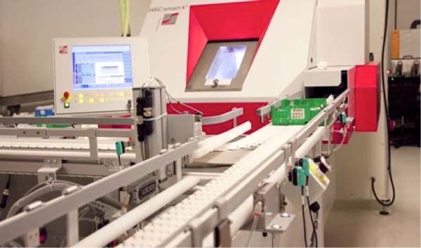
LAB MANAGEMENT SYSTEM (LMS)
An LMS is essentially the brain of the optical lab. One of its main functions is to perform all the calculations necessary to create a pair of lenses. Every step we discuss from this point forward has in some way been affected by the LMS. When prescription info (Rx, frame, POW) is received by the LMS, a job is created. The job is assigned a unique identifier, usually in the form of a tray number. The tray number is used to track the job throughout the lab, but it’s also used by the equipment to ensure proper processing. When the tray number is entered into a machine, it asks the LMS “Hey LMS, this is the generator! I have tray 4200 in front of me. What the heck do I do with it?” The LMS then responds with “Hello Generator, great to hear from you! Tray 4200 requires the following curves to be cut in the back of the lens.” Think of the Tray Number as the job’s name. Instead of calling it Fred (there can be only one Fred at a time), the lab calls it 4200.
FRAME TRACING
The LMS can’t calculate a lens without frame measurements, just like an artist can’t paint their masterpiece until they know how big the piece is going to be. The Rx and patient measurements aren’t enough information because the frame is what determines the Minimum Blank Size (MBS) and, therefore, the lens thickness. The MBS is the smallest lens blank that can be used for a given frame. If the MBS is calculated incorrectly, the lens may be too small, which can’t be fixed, or too big, which can be fixed, but will result in a thicker lens. The formula for MBS relies on the Effective Diameter (ED) of the frame. ED being 2 x the longest radius of the frame.
Min. Blank Size = Effective Diameter + (2 x Decentration) + 2mm
Note: The + 2 mm is an optional value. It’s used as a safeguard in case the measurements for ED or decentration are a little off. Remember, we can make a big lens smaller, but a small lens is breakage.
Example: A job comes in with the following information: A = 52, B = 44, ED = 56, DBL = 16, Patient PD = 33 OU
The monocular “frame PD” is (A + DBL)/2 = (52 + 16)/2 = 34 mm. The decentration is the difference between the patient PD and the frame PD or 34 – 33 = 1 mm. Now we have enough information to calculate the MBS.
Min. Blank Size = 56 + (2 x 1) + 2mm = 60mm
This means we need to select a lens blank with a diameter of no less than 60 mm to ensure the lens shape will cut out properly. We wouldn’t know that unless we had frame measurements!
Having said all this, the most accurate frame measurements are achieved using a frame tracer. Using a PD stick to obtain MBS will only get you a rough measurement accurate to about 1 mm. A tracer can provide measurements accurate to less than 1 mm. Here’s how it works: You place the frame into the tracer and a small stylus runs through the grooves of the eyewire, saving information along the way. For example, a tracer might have a 1,000 point resolution. This means it saves 1,000 pieces of information for each eye to be used by the edger for cutting the proper lens shape. This is done the same way if the job is freeform or conventional.
CALCULATING THE JOB
When calculating a conventional lens, the LMS can handle the job. It can calculate things like thicknesses and prism. There are limitations, though. It can’t calculate complex backside freeform surfaces. It needs some help, which we’ll address when we discuss the Lens Design System (LDS).
Freeform lenses are a bit different. One of the first things you’ll notice about a freeform job received from the lab is that the power readings may be different from those prescribed. This is the Compensated Rx. It’s different because the compensated Rx takes the position of wear (POW) measurements into consideration. Here’s where there has been some confusion. The compensated Rx values are for lens inspection only. They are not the Rx that will be perceived by the patient. The compensated Rx is saying, “At inspection, if you read these numbers in your lensometer, the patient will be getting the Rx prescribed to them.” Below are some examples of how POW affects the perceived power of a lens.
Vertex Change - If the patient wears their lenses at a distance other than what was set on the phoroptor (usually 13 mm), there will be a change in perceived power. It can be roughly calculated using the following formula:
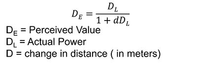
Note: Use -d if the lens is moving away from the eye, use +d if the lens is moving toward the eye.
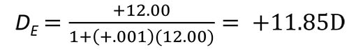
This tells us that we had a 0.15 diopter of perceived power difference for every 1 mm change in the vertex distance. If the change were 2 mm, the perceived power would differ by more than a quarter diopter!
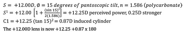
Pantoscopic Tilt - As we said earlier, the lenses in the phoroptor are parallel to the cornea, but most eyeglass frames’ bottom rims have a slight inward tilt (sit closer to the face). This lens tilt will alter the sphere power and induce cylinder.
To calculate the new sphere, cylinder and axis, the following formulas are used:
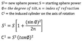
Using the following values for these variables, calculate the change in power induced by pantoscopic tilt:
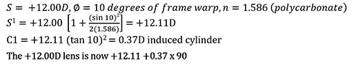
Wrap - The calculations for wrap are the same on a vertical axis instead of horizontal.
LENS DESIGN SYSTEM (LDS)
The backside surface of a freeform lens is based on very complicated ray-tracing algorithms. Ray tracing is basically a simulation run by the LDS that considers frame measurements, POW measurements, frame data, the patient Rx, and the natural motion of the human eye. It then uses the results of this simulation to calculate a backside surface that’s optimal for all positions of gaze for that patient. The LDS then produces a Surface Definition File (SDF) that contains a matrix of values which represent the freeform design. The SDF file is used by the Computer Numeric Code (CNC) generator to cut the complex surface in the back of the lens. It takes a whole lot of very smart people to create the LDS computer algorithms. These calculations are what truly separate conventional and freeform progressive lenses.
LENS PICKING
Once all the calculations are complete, the lens blanks can now be picked from inventory. The LMS will print a workticket that contains all the information the lab needs to process the job, including which lens blanks need to be used. In the lens pick area, there are racks of lenses in boxes or paper sleeves, each with a barcode called an Optical Product Code (OPC). The OPC is a unique identifier for ophthalmic lenses and is used all over the world.
When choosing conventional progressive lenses, we must keep in mind “chirality,” which comes from the Greek word for hand. There will be a right-hand lens and a left-hand lens. This means the OPCs on the Work ticket will be different for the right and left lens.
Selecting freeform lenses is much simpler because they use what’s called single vision “donor” lenses. These lenses aren’t chiral because the progressive design isn’t added until later. They’re essentially just single vision lens blanks with the selected base curve on the front. Once the lenses are removed from the boxes or sleeves, a protective layer of tape is placed over the front surface of the lens. This keeps the surface from being scratched while traveling through the surface department.
SURFACING
A surface blocker is a device that attaches a block to the (taped) front surface of a lens. The surface equipment clamps onto this block and provides a solid surface for the surfacing tasks ahead. This is a crucial step in the process because this is also where the lens is decentered for correct optical center placement and the prism is added. If the lens has cylinder, the axis is set. If you make an error here, there’s a good chance the lens will not pass inspection. Luckily, modern blockers have an LCD screen that displays the lens in the blocking position with an overlay of the correct placement. You simply line up the lens with the overlay.
Blocking a conventional progressive is a bit challenging. There are a few things you must watch for. You must ensure the distance portion is in the correct position, and the axis is aligned. Blocking a freeform lens is much easier. The blocker displays a circle on the screen, and you simply make sure the lens is in the circle.
GENERATING
The generator is a machine that utilizes cutting tools to remove most of the unneeded material from the back surface of the lens. It gets us close, but not quite to the prescription we need. For conventional lenses, the first generating step is to remove unneeded material from the perimeter of the lens. This is known as cribbing. Next, the machine carves out the Rx on the back of the lens. This single milling bit can create the sphere and cylinder cuts for conventional lenses.
Freeform lens surfacing uses a diamond-point lathe to cut the complex back surface. When generating a freeform lens, it’s cribbed, and the back surface is cut with the milling tool, just like a conventional lens. The difference is the freeform generator has an extra step that uses a tiny diamond lathe to cut the complex curve into the lens. The generator gets the information to make this cut from the Surface Definition File mentioned earlier.
POLISHING
The polisher performs the crucial step of removing the last bit of material, thereby completing the prescription. Polishing conventional lenses is a multi-stage process. The first step is to retrieve a lap tool. A lap tool has a convex surface that matches the lens’ concave back surface. Laps are made from metal, PVC plastic or hard foam. For lenses without cylinder, the lap tool is described by a single number representing the back base curve, 2.00, for example. If the lens has cylinder, the lap will have two numbers, let’s say 2.00|1.00. This means the lap should be used on lenses with a 2.00D back base curve and a 1.00D cross curve. If you happen to grab the wrong lap, which is easy to do when you’re in a hurry, you could remove too much or too little material from the back surface, which could result in breakage, much to the displeasure of your boss.
Next, a star-shaped piece of sandpaper material is placed on the lap. When the polishing process begins, a continuous flow of cold water is pumped onto the lens to cool it. This process removes about 3/10 mm of material. The generator is used to remove the bulk of excess material, but the polisher finishes the job.
When the first polishing step has been completed, another one is performed with a polishing pad that’s less rough than the first one. Also, the water is replaced with a liquid polishing solution. This step removes only a few microns (thousandths of a millimeter) and results in an optically clear lens.
When freeform lenses come out of the generator, the back surface is nearly complete. This is because the diamond lathe is very precise when cutting the freeform design. A fine polish is the last step in freeform lens production to make the lens optically clear. Freeform lenses don’t use the same lap tools as conventional jobs because the complex surface would be removed by a hard metal or plastic lap tool. Freeform polishers use something called a soft lap, which is essentially an abrasive pad mounted on a piece of soft foam. This allows the pad to conform to the complex freeform surface and remove the final microns of material.
LASER BEAMS!
Once the freeform lenses are polished, markings need to be engraved on the back surface. These markings will be used later for inspection and to prepare the lens for edging. They include two small circles spaced 34 mm apart. Under the circle on the nasal side, the logo of the freeform design is engraved and on the temple side, the add power. The markings are laser etched into the back of the lens. Engravers usually use an excimer or ultraviolet CO2 laser. Conventional progressive lens blanks lenses already have markings on the front of the lens, so they don’t need to be zapped.
SURFACE INSPECTION
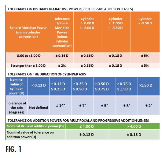
Now that the lenses have been surfaced, we need to inspect them to ensure they conform to the prescription. What if the measured values don’t exactly match the prescription? Do we chuck them in the trash? No! Fortunately, we’re allowed some variance. The amount of variance is determined by the American National Standards Institute (ANSI). Fig. 1 shows the the ANSI standards for distance, cylinder axis and add power.
Let’s inspect a pair of lenses and use the ANSI standards to see if they’re acceptable.
Prescribed Rx: O.D. +3.12, O.S. +3.45 Add +2.00
The results of the inspection are: O.D. +3.30, O.S. +3.55, Add +2.10
The prescribed O.D. sphere power is +3.12, but the inspected sphere power is +3.30. That’s a difference of 0.18 diopters. If we look at the tolerance on distance refractive power for progressive addition lenses, we see that for prescriptions between -8.00 to +8.00 (which +3.12 is), we’re allowed plus or minus 0.16D. This lens fails inspection.
CONCLUSION
I hope you have enjoyed the journey of a pair of ophthalmic progressive lenses through a surfacing lab. From here, the lenses might be coated, then edged and inserted into the frame, but we’ll save that for another course.