
By Barry Santini
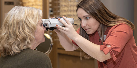
One of the basic tasks in ophthalmic dispensing is measuring the distance between a patient’s pupils, a prerequisite for properly positioning and fitting eyeglasses. The tools for doing this range from simple PD rulers to digital pupilometers (also spelled “pupillometers”) to sophisticated digital centration systems that allow for various other measurements to be taken.
This article will explain some basic pupillometry techniques along, with some ophthalmic optics principles as they relate to vision and eye movement.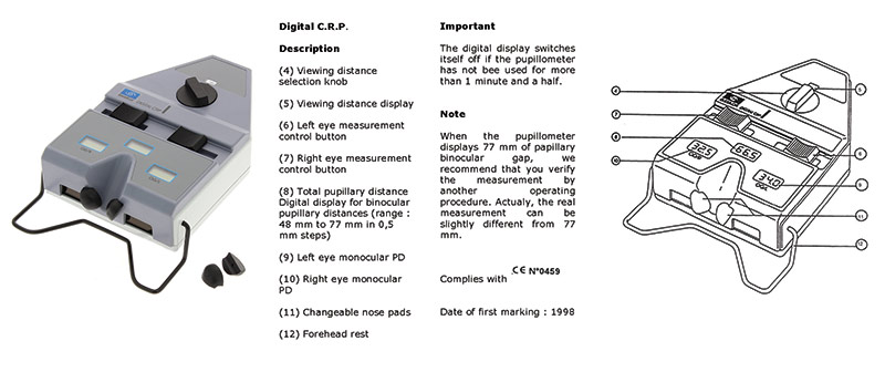
Photo: Essilor Instruments
USING YOUR PUPILOMETER
For starters, we’ll assume your favorite pupilometer is in proper operational order and properly calibrated—meaning the PD values found are accurately indicated by the instrument’s scales. With an instrument assumed to be in good order, always keep the following areas of potential error in mind. By doing so, you’ll reduce the uncertainty in your measurements:
Parallax: Not every pupilometer is designed to reduce error from operator-induced parallax. The easiest way to check if your pupilometer is susceptible to operator parallax is to move your eye position closer to and further away from the eye viewing port while taking various PD measurements. If you notice the alignment marks shift with respect to the patient’s corneal reflex, you have parallax. Find the most parallax-free point by experimenting with your eye position until the shifting of your gaze as you mark the right and left eye produces the least apparent shift of the alignment mark against the corneal reflection.
Forehead rest: The forehead rest bar was designed to align the pupilometer’s reference scales to an equal vertex distance from the eye. Oftentimes, when the vertex distance between the eyes is not symmetrical, errors of parallax might affect the monocular values found. Therefore, the operator must ensure the forehead bar is in equal contact with the patient’s forehead. In all cases, the operator should take a bird’s eye view of the patient’s forehead and eye placement, and note where any forehead asymmetry could impact the accuracy of the values found. In some cases, patients will also slowly rotate their head during the measurement process, which will also impact accuracy.
Phorias: Some patients, especially without their habitual Rx in place during the PD measurement, will reveal a latent phoria which will impact the final measurement accuracy. Good pupillometry practice therefore dictates taking the PD monocularly, using the occlusion bar and noting any measurement differences indicated.
Visual observation: As a double check, I recommend always taking PD readings at least twice and in between readings—looking up at the patient’s eyes to confirm that the readings relate to both any asymmetry or symmetry found. In addition, I also perform this visual double check when measuring pupil heights.
REFLECTIONS ON THE REFLEX
The corneal reflex, typically located approximately 1 mm nasalward of pupil center at the spectacle plane, has been considered the most accurate marker for the eye’s visual axis. This lateral shift means a binocular PD taken using the corneal reflex is typically near 2 mm narrower at the spectacle plane than one measured using pupil center. Maximizing intermediate utility is the goal when fitting progressives, while unwanted prism imbalance is reduced when fitting single vision lenses. Further, using the corneal reflex assures proper alignment of the prism reference point (PRP) of freeform single vision, single vision, boost and progressive lenses. This centers the lens as the designer intended. In view of the corneal reflex’s many advantages, it remains interesting that even the current ANSI standard does not specify whether its listed tolerances are to be referenced to pupil center or corneal reflex values. So every optician should align their lenses to the corneal reflex, right?

Western Optical Supply’s ruler #2069 can be used to take binocular PD, monocular PD, seg height, dbl of frame and more
WHEN THE REFLEX DEPARTS
Well... yes and no. What every optician should know is the why, where and when the corneal reflection may not represent where the visual axis exits the eye. Amongst the theoretical reasons for departures are:
- Variations in axial length: Overly short axial length—strong hyperopia and overly long axial length—strong myopia, can shift the location of the eye’s nodal points. These nodal points are a checkpoint for where the visual axis departs from the eye’s optical axis. The angle created by this departure is generally referred to as angle kappa and is near the center of rotation in most eyes.
- Variations in angle kappa: The angular separation between the pupillary axis and the visual axis is referred to as angle kappa and has an averaged value of 5 degrees. But the envelope of real-world values found ranges from as low as 2 degrees to as high as 9 degrees.
- Variations in foveal location: As mentioned above, the fovea’s horizontal location on the fundus, with respect to the posterior pole of the eye, ranges between 3 and 4 mm. The specific angular location of the fovea with respect to the eye’s optical axis clearly influences the value of angle kappa.
- Distorted corneal topography: Any regional anomaly near the corneal apex—the area which optically determines where the reflection of a coxially mounted light surface will lie—can impact accurate determination of the visual axis’ location.
- Variations in vertex distance: Along with variations in axial length, vertex distances that depart significantly from the mean value of 13.5 mm will clearly impact near vision PD values.
A GLOSSARY FOR UNDERSTANDING VISUAL AXIS
The human eye is a complex multi-element optical system, where the main refracting elements—cornea and crystalline lens—do not inherently have their centers of curvature precisely aligned to one axis. However, researchers have simplified the alignment of the various axes in the eye to facilitate defining the vocabulary differentiating the alignment of the eye globe versus where the fovea is pointed, which is what marks where the eye is actually looking. Here are some useful terms:
Optical axis: The optical axis of the eye closely connects where the centers of the cornea and lens curvatures lie and aligns closely—but not precisely to the geometric center of the pupil.
Posterior pole: For the purposes of this discussion, the posterior pole will be considered the point on the fundus where the optical axis intersects the retina. (In a broader definition, the posterior pole is referred to as the area lying between the macula lutea and the optic disk.)
The pupillary axis: Defined as a ray normal, meaning perpendicular to the surface of the cornea and directed to the center of the pupil.
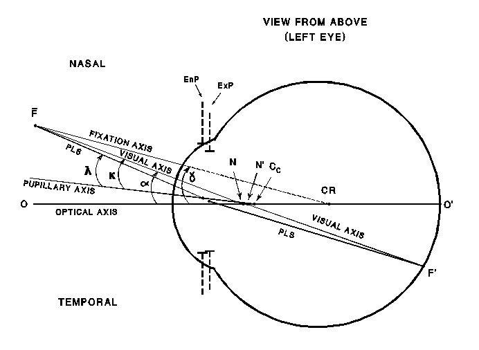
The visual axis: Because the fovea is offset between 4 and 8 degrees temporally from the posterior pole, the visual axis, defined as a line emanating from the fovea representing where the eye is actually looking, is also displaced from and no longer parallel to the optical axis. The visual axis therefore crosses over the eye’s optical axis and exits the corneal nasalward of the geometric center of the pupil.
Cornea center of curvature (CoC): An important reference point used when conceptualizing the cornea as a mirror or reflecting surface. When ray tracing the position of a corneal reflex created with a coaxially mounted light source, the reflex’s location is located by a ray that passes through the cornea’s CoC. The cornea CoC by definition lies on the optical axis.
Nodal points: One of the cardinal reference points used in evaluating an optical system, the nodal points of the eye are located where the visual axis, on its way from the fovea to then cornea, crosses over the optical axis. The key to understanding why we use the corneal reflex as a marker for the position of the visual axis is that the nodal points are located so close to the cornea’s CoC that the resulting corneal reflex is considered to mark where the visual axis exits the cornea. (See Diagram A)
Aligning to the corneal reflex recognizes that the eye uses the fovea and not the posterior pole when fixating on an object. And because corneal reflection measuring instruments sit where the finished spectacles would also lie, the values obtained indicate where the visual axis intersects the spectacle plane.
-BS
Source: National Board of Optics Study Guide
CAN WE BE OBJECTIVE ABOUT ANGLE KAPPA?
With all of the potential factors influencing the angle kappa value found in any patient, it is good pupillometry practice to be realistic or digital centration device—can be truly free of the influence of the instrument, operator or patient unintentionally affecting the results. This was the conclusion of an exhaustive PD measuring study published in 2010 by the British journal Optician, by Dr. Wolfgang Wesemann, titled “Comparison of PD Measuring Devices.”
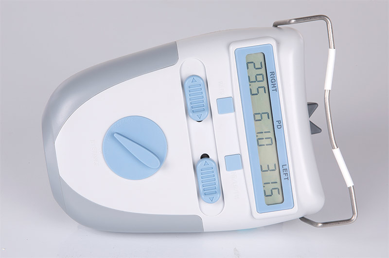
Western Optical Supply’s DigiOmeter Digital Pupilometer #2061DP3 can take vertical pupillary height readings
SUBJECTIVITY RULES
Dr. Thomas Clark, OD, has been researching using objective modalities for measuring the accurate location of the visual axis and has found them all wanting. Dr. Clark recommends using a subjective method—one where the patient actively participates in indicating where their eyes are actually looking—to bypass the pitfalls of an objective approach and obtain accurate visual axis values. Although this approach is not new—William Feinbloom developed a subjective method for precise monocular near measurement in his 1966 patent for a telemicroscope bifocal loupe—subjective methods for measuring PDs have, up until now, not seen broad industry acceptance.
WHO OWNS THE PD?
The pupillary distance, or PD, has become a contentious and public issue in the early 21st century. For most of the past 80 years, the PD was measured primarily within the offices of optometrists and opticians. But the arrival of online and multichannel distribution of prescription eyeglasses has massively politicized the PD—morphing it from being a simple measurement of the distance between the eyes into a question of risk control versus consumer freedom of choice. With prescription eyewear sales increasingly fragmenting away from the traditional optical office, the public is confronting eyecare professionals with an important question: “Who really owns the PD: The ones taking it, or the individual having it taken?”With the public increasingly requesting their PD, what’s the motivation for ECPs to continue a commitment to achieving maximum accuracy and precision, only to have all your hard work freely given away? You must decide for yourself how you will navigate this and the rest of the disruptive optical world we find ourselves in today. I, for one, will continue to be as accurate as possible in all my measurements. But at the same time, I remain fully informed how the fabrication chain, patient posture and the realities of frame fit can impact the pursuit of PD excellence.
The more prickly question of whether to share or withhold a patient’s PD is, I feel, less about whether you’re helping your online competition and more about helping the one entity your optical business cannot long survive without—the local eyeglass consumer. Ask yourself: Is the potential impact of negative word of mouth or an online review really worth withholding anyone’s PD? A better approach would be to integrate this discussion into a review of how your store’s total eyewear experience is being received and reviewed by the public. Clearly, this experience is far more important to your long-term bottom line than any petty PD issue. In business, it is said that if you take the long view, there’s a much better chance your customer will too.
-BS
CALCULATING A PROPER NEAR PD
Taking a proper near PD involves taking a lot of factors into account. Here’s a quick list of the various moving parts impacting near PD and how they are measured:
- Spectacle vertex distance (VD): Measured via a vertex gauge or digital centration device.
- Center of rotation distance (CoR): Formally determined through analysis of the displacement of the corneal reflex during eye rotation, today there exists a wealth of CoR data derived from the Rx calculations made prior to intra ocular lens insertion—aka cataract surgery—to predict with a high level of confidence where the CoR lies relative to the degree of ametropia.
- Fixation distance: Also known as the functional reading distance, this value, combined with the distance PD and the VD, forms a triangle important when calculating where the near visual axis intersects the spectacle plane.
- Distance Rx: In multifocals and progressives, the prismatic effect of the distance Rx should be taken into account when determining proper inset of these lenses.
- Frame wrap angle: Most near PD calculations assume a flat spectacle plane—aka “0” degree wrap angle. Wrap angles greater than 3 to 4 degrees—quite common in today’s frames—must be taken into account when determining near centration.
A BRIEF HISTORY OF PD MEASUREMENT
Sixty years ago, the arrival of Varilux—the first commercially successful progressive lens—put the simple PD on a path to become anything but simple. The need for a more complete understanding of just what it means to “take a PD” has in large part been driven by the increased sophistication and complexity of personalized freeform lens technology, along with a renewed sense of the importance of optimizing binocular vision (BV). To their credit, most optical offices have moved on from using a shop ruler to modern digital devices when taking a pupillary measurement.
Yet there remain ardent holdouts of the ruler—citing that their support of this measuring method has not turned up any “bodies”—meaning any evidence of clear or lasting harm. But I respectfully submit that this sentiment goes right to the central core of what may be wrong with most opticals today: A continued reliance on the status quo, with little desire to better understand the evolving body of knowledge and changed consumer climate that’s unfolded since the fitting of flat top bifocals and trifocals was an everyday occurrence. To discover more, let’s look at the history of taking PD measurements and the technical theory that informs modern pupillometer design along with the latest digital centration devices.
PRISM AND PLACEMENT
In the first half of the 20th century and certainly from the mid 1930s onward, the movement toward certifying those who measured, made and dispensed eyeglasses—the opticians—actually grew out of the same public protectionist sentiment as Prohibition. The thinking behind the movement was to free spectacle wearers from any dizziness and discomfort that could ultimately be traced back to having to get used to glasses made inaccurately in prescription or lens centering. There certainly was enough stigma attached to the wearing of eyeglasses to not further ask buyers to suffer because of improperly made specs.
With a doctor’s Rx in hand, the optician’s main responsibility is to fill it accurately and ensure that the lenses are properly centered. Improperly centered single vision lenses could have unwanted prism or prism imbalance, creating headaches and/or double vision, while misaligned multifocals could become a tripping hazard or produce undue head and neck strain for the wearer. The half century spanning from the 1920s to the 1970s was the age when binocular PDs ruled, and little recognition was given to monocular centering considerations. This was, in large part, because the nonsymmetrical appearance of lined segments only served to call more attention to wearer’s vision deficiency. The problems with using a traditional binocular PD was mostly revealed with the dawn of progressives in the 1960s.
PROGRESSIVES AND PLACEMENT
The main difference between the centering of early progressives and conventional multifocals lies in recognizing how unforgiving progressives were in ensuring maximum utility of the reading zones. First and second-generation progressives had very small reading areas—roughly equivalent to a FT bifocal segment of 10 mm to 12 mm wide—with intermediate corridors not much larger than 3 to 4 mm wide. These narrow windows, half the field size of common 22 mm to 25 mm segments of the day, along with decreased clarity in the peripheral distance areas uncovered why relying on a traditional binocular PD could decrease comfort and visual utility.
WHEN RULERS RULED
When using a ruler, the PD value is referenced to the center of the pupil. This is actually a measurement of the eye’s pupillary axes separation. The pupillary axis is defined by a ray directed to the center of the pupil, normal to the surface of the cornea. For the first half of the 20th century, taking a binocular PD via millimeter ruler was found to be more than adequate for the simpler lenses of the time. The ruler method, however, came with an inherent flaw: operator-induced parallax. At the time, this parallax error went often unrecognized, misunderstood or overlooked, and the resultant binocular PD value was considered to be “good enough,” i.e., no complaints heard. However, when opticians had to begin taking monocular PDs freehand via ruler, this measurement was found to be far more influenced by both operator and patient parallax, compounded by a lack of a clear bridge reference for how the chosen frame will sit. And remember that near PDs are even more susceptible to parallax-induced errors.
ENTER THE PUPILLOMETER
Although pupillometers existed before the 1970s, Varilux and other lens companies of the day—American Optical and Titmus—each brought to market their own newly-designed pupillometers, which improved on the task of taking accurate monocular PDs in two ways:
- By providing a rest point on the bridge similar to an eyeglass frame, pupilometers provided a proper reference point for obtaining an accurate monocular PD value.
- These latest instruments differ in their approach to the ruler/pupil center method by sighting the corneal reflection with the use of a coaxially-mounted light source—which eliminates the parallax error inherent when the fixation light is not on the same axis as the operator. This corneal reflection—or reflex—most closely represents where the eye’s visual axis intersects the corneal plane.
-BS
PD PRECISION AND THE FABRICATION CHAIN
No matter what your favorite measuring modality is, every ECP should be aware of the potential factors in the spectacle fabrication chain that can reduce both PD accuracy and precision:
- Data entry rounding: Most PD values are recorded to a precision of 0.5 mm. But the latest frame-based digital measuring systems can deliver corneal-reflex PD values down to 0.1 mm. This extra precision may be lost when using a lab ordering portal. Even if the entry field accepts an entered value of 0.1 mm, the back end of the lab’s management system (LMS) may be rounding your values to the nearest 0.5 mm.
- Frame wrap angle: The blocking of lenses in preparation for edging has traditionally assumed that the wrap angle of the frame in question is close to zero. When the frame wrap angle exceeds 4 degrees, a compensation must be made to the PD values to ensure the spectacles finish to the original PD measurement. Luckily, most of today’s frame tracers can be configured to make this compensation automatically. However, problems will arise with rimless and semi-rimless frames as these styles trace only one lens, with the lab technician manually entering the frame’s labelled DBL value. Overlooking the entry of either a PD or DBL value adjusted for frame wrap angle will result in a too-narrow finished binocular PD value. With many of today’s wrap angles routinely exceeding 8 degrees, any lack of addressing this error area will cancel a lot of hard work in measuring the PD by the ECP. In addition, maintaining accurate finished centration through the life of the spectacles can be elusive arising from the frame front flattening arising from daily use, handling habit or improper storage can change lens centration.
- Verification parallax: When it’s time to verify a finished pair of glasses, the measurement of the PD using a protractor can be influenced by parallax between the plane of the lenses and the protractor scale. Particularly with sports frames, which routinely have wrap angles between 18 and 27 degrees, the error can amount to as much as 2 to 3 mm.
Of course, the worst-case scenario can exist where all of the fabrication chain errors add up in a very undesirable way. Diligence and understanding where the errors can originate from is the responsibility of every person handling the eyeglass order.
UNDERSTANDING THE INFLUENCE OF EYE DOMINANCE
Most people have a dominant eye, meaning an eye whose vision the brain broadly favors. Although eye dominance often follows handedness, it is not to be assumed. But the reason that eye dominance is important to the question of accuracy in PD has been put forth by our favorite PD guru, Dr. Thomas Clark. Dr. Clark sees eye dominance as influencing how ECPs might rethink how they apply ANSI tolerances to progressive centration. Instead of applying a fabrication tolerance to each eye, Dr. Clark suggests a progressive wearer will naturally align and center the dominant eye’s progressive corridor through minor head rotation, thereby placing the full binocular error present into the companion eye. With a 1 mm per eye stated ANSI tolerance, this can amount to a companion eye error of as much as 2 mm—not something most wearers would tolerate comfortably.
THE PD IN THE AGE OF THE ONLINE CONSUMER
As consumers increasingly fragment buying their Rx eyeglasses online, the B2C channel is actively offering direct assistance for getting that oh-so-essential measurement without the drama or emotional baggage that often accompanies asking their local doctor’s office. Through various measuring apps and instructional techniques—some using a simple credit card as the ruler scale—consumers may feel empowered and confident that the PD obtained in this manner is “good enough.” But is it? Here’s a quick list of the common pitfalls:
- Phone and facial parallax: Here, yet again, parallax errors can arise from either the plane of the credit card or the wearer’s head not being perpendicular to the camera’s optical axis. If the app includes virtual try-on (VTO) of the chosen frame, the actual fit of the real world frame may not correspond to the VTO rendition.
- Unwanted convergence: This is the most insidious contributor, as it is almost impossible to get an untrained consumer to provide a distance fixation while looking at a proximal mirror or camera.
- Phorias revealed: Without their habitual Rx in place and along with the parallax and convergence issues noted above, many consumers can reveal a latent phoria, particularly in closer focus situations. These eye posture deviations—addressed by the ECP through the separate occlusion of each eye in the pupilometer—will obviously influence the accuracy of the PD results.
Therefore, it is very important for every ECP to convey to their patients how important their years of experience and advanced instrumentation are in reducing the uncertainty inherent in PD measurements and always ensuring the accurate alignment for needed maximum comfort. Just speaking with confidence goes a long way to increasing patient trust and confidence in the measuring process. No matter what price paid, every eyeglass wearer is entitled to good, comfortable vision.■
BEYOND THE PUPILOMETER
Digital centration devices can measure PDs, vertex distance, pantoscopic tilt and more. Here’s a quick look at some of the latest products and technology.
 Essilor Instruments Eye-Ruler 2: An all-in-one compact device enabling personalized measurements with only two photos as well as a frame comparison. essilorinstrumentsusa.com/ products/dispensing/eye-ruler-2
 Hoya’s Spectangle Pro: An iPad app that assists in every facet of the eyewear dispensing process—frame selection, lens demonstrations and eyewear measurements—using one single image. spectanglepro.com
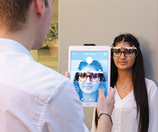
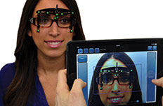
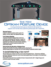 Optikam Posture Device (OPD):
Demonstrate the benefits of multiple pairs of eyewear by capturing various postures of the customers (sitting, standing or driving) and one single image.
optikam.com
Optikam Posture Device (OPD):
Demonstrate the benefits of multiple pairs of eyewear by capturing various postures of the customers (sitting, standing or driving) and one single image.
optikam.com
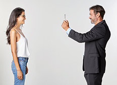
 Shamir Spark Mi Up: A touchless measuring device that allows ECPs to take all required measurements with just a few clicks, while keeping patients at a safe distance.
shamirlens.com/sparkmiup
Shamir Spark Mi Up: A touchless measuring device that allows ECPs to take all required measurements with just a few clicks, while keeping patients at a safe distance.
shamirlens.com/sparkmiup
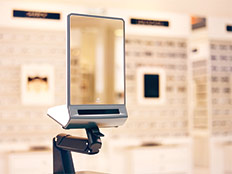
 Smart Mirror for iPad Pro, iPad OS 14: The Smart Mirror for iPad Pro and iPadOS 14 from ACEP USA is the latest version the company’s iPad-based measuring digital device. It does not require the use of a cumbersome frame clip to measure PDs and heights quickly and accurately, and all the other measurements necessary to ensure a proper lens fit.
opticvideo.com
Smart Mirror for iPad Pro, iPad OS 14: The Smart Mirror for iPad Pro and iPadOS 14 from ACEP USA is the latest version the company’s iPad-based measuring digital device. It does not require the use of a cumbersome frame clip to measure PDs and heights quickly and accurately, and all the other measurements necessary to ensure a proper lens fit.
opticvideo.com
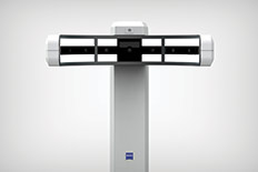 Zeiss Visufit 1000
The Zeiss Visufit 1000 features one-shot 3D digital centration, using nine cameras to capture a 180 degree view of the patient’s face with a single shot. The device also offers frame comparison and virtual frame try-on in 3D.
bit.ly/3a31fKA
Contributing editor Barry Santini is a New York State licensed optician based in Seaford, N.Y. In researching this article, he acknowledges the help of Dr. Thomas Clark, who first opened his mind to the importance of angle kappa and eye dominance. He also credits The Academy of Advanced Ophthalmic Optics, particularly their educational YouTube videos, as an excellent resource for ECPs.