
By Palmer R. Cook, OD
American astrophysicist and author and science communicator Neil deGrasse Tyson once tweeted, “If shrunk to a few inches across, Earth would feel as smooth as a billiard-hall cue ball.” Actually, the surface of an ophthalmic lens has something we have spread across the entire surface of our planet. That something is the system of latitude and longitude, a concept which works well over both curved and flat surfaces. We are consistent in using longitudes (e.g., interpupillary distance), but latitude (e.g., needed for MRP location) is a coordinate too often overlooked.


LONGITUDE AND LATITUDE
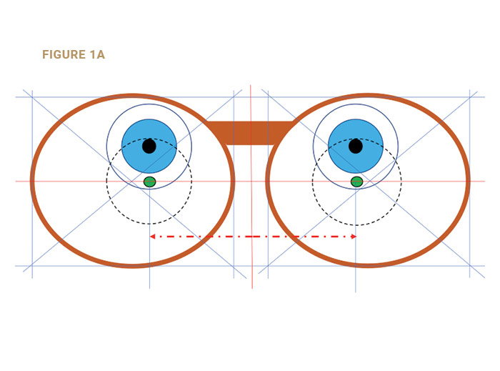
Placement of the MRP or the Fitting Cross (FC) for any lens is fixed by two coordinates determined by you. Just as both longitude and latitude are needed to find any location on Earth, both the PD (longitude or east-west positioning on a globe) and MRP and FC height (latitude or north-south positioning) are needed to locate the MRP or FC of a lens.
The coordinate (latitude) for either the MRP or FC is located from the bottom of the boxed dimensions of the fitted frame (Fig. 1a). For the PD (longitude) the measurement is horizontally from the centerline of the frame’s DBL to the chosen landmark (e.g., center of the pupil, anterior corneal reflex, or the line-of-sight) of each eye.
Many ECPs fail to supply the MRP height. As a result, labs set rules for MRP placement when they are not supplied in the order. This practice tests the tolerance of many of our patients. Some will return to the prescribing doctor because of trust, convenience, or habit, but many will search to find more satisfying eyewear, or eyewear which presents fewer adaptation problems. Unfortunately, it is a rare optical dispensary that provides truly better eyewear. Errors and omissions such as ignoring the MRP height when measuring are common throughout the eyecare industry.
DEFINING THE PD
The PD, or interpupillary distance, has been casually termed as the distance between the centers of the pupils. That worked well enough for single vision lenses, but then Ben Franklin created bifocals, and they had relatively large reading areas. As other bifocal designs were developed, it became common practice to move the centers of the reading areas inward to allow full use of the width of the segments.
A definition from Dr. Borish’s classic textbook, Clinical Refraction, 2nd Ed. 1954, states, “The interpupillary distance (PD) represents the separation of the centers of the entrance pupils, which are on the line of sight.” This is correct, but it can easily be misleading to optometry students, apprentice opticians and others new to the ophthalmic industry.
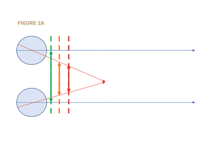
For eyewear purposes, the PD is the separation of the points at which the lines-of-sight intersect the lenses. For viewing distant objects the lines-of-sight are parallel, so their separation is the same at the pupillary plane, at the spectacle plane and at all distances. That is not true of the near PD (Fig. 2a).
MRP HEIGHT
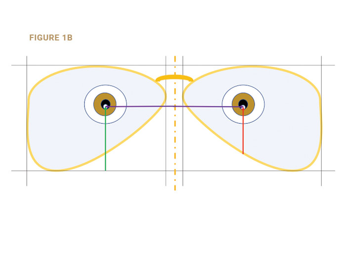
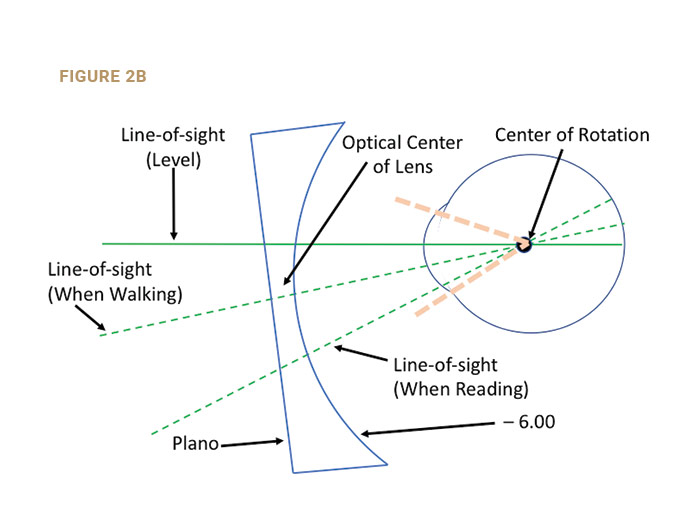
The MRP height is the vertical distance from the bottom of the “Box” (the lowest point of the lens) to the MRP (Fig. 1b). The MRP height should be measured after the frame is correctly aligned. The placement of the MRP should be 1 mm below the pupil center for every 2 degrees of pantoscopic tilt (Fig. 2b). If the OC was at the pupil’s center (Fig. 2a), the lens performance on down-gaze would be compromised.
In Fig. 2b, the OC was lowered so the line-of-sight on down-gaze would pass through the lens at an angle more normal to the lens curvatures. Pantoscopic tilt was added which shortens both distance and near vertex distances. This widens the corridors and the near reading areas, which is appreciated by patients. The lateral canthus is located about as far posterior to the cornea as the center of rotation. Therefore, you can view the patient from the side as he looks down at his normal reading angle and estimate if more or less pantoscopic tilt might be needed. In most cases, a line extending from the patient’s object-of-regard to the corneal apex will appear to align with the outer canthus. It is easy to estimate whether that line is approximately normal to the lens surfaces. A good rule of thumb is to place the MRP 1 mm below the pupil’s center for every 2 degrees of pantoscopic tilt. If the pantoscopic tilt is 8 degrees, then the MRP would be two-thirds of the way from the pupil’s center to the lower limbus.
PALS (PROGRESSIVE ADDITION LENSES)
Each PAL design specifies the separation of the DRP, PRP and NRP from the Fitting Cross. This system eliminates much of the confusion related to the early PAL designs, but it introduces other issues. Since the MRP is split into a DRP and PRP, there is no one point in most PAL lenses at which the patient’s line-of-sight achieves the correct refractive power for either distance or near seeing combined with the exact prism or lack of prism that the doctor has specified in his prescription.
This splitting of the MRP was done to create thinner lenses. The doctor or the optician who recommends PALs assumes the responsibility for that patient’s comfort and visual performance just as with any lens design. Since the refractive power prescribed for distance is not available at the PRP, and the prescribed prism power is usually not available at the DRP, patients’ vision can be compromised. This can be addressed by adding prism to move the OC to (or near) the DRP, although this will increase thickness and weight.
YOKED PRISM EFFECT
Yoked prisms are prisms with their bases in the same direction. Images seen through the lenses will be displaced away from the base of each prism. PALs sometimes use yoked prisms to reduce both weight and thickness.
There is evidence that up to about 2∆ prism diopters of vertical yoked prism is tolerated, between 2∆ and 3∆, but patients may expect some adaptation difficulties. At 4∆ or more of yoked prisms, the lenses can strongly affect adaptation and cause postural changes. Checking the amount of yoked prism at the DRP and NRP prior to dispensing is a good practice.
A PAL with a distance Rx of +3.50DS OU and a PRP-DRP separation of 10 mm, would have 3.5∆BD OU at the DRPs. If 1.5∆ BD of prism thinning was added by the lab at the PRP, the total yoked prism effect at the DRP would be 5∆ in each eye. If 1.5∆ BD of prism was added by the lab at the PRP, the total yoked prism effect at the DRP would be 5∆ in each eye. A lens design with a low power gain at the upper end of the corridor could allow the patient better distance vision below the DRP, and by using a frame with a short B measurement the prism thinning might be avoided. A consultation with your lab is a good idea in cases of this sort.
PRISM DISPLACEMENT OF MRPS AND FCS
If 3∆ BI is prescribed, the monocular PDs would need to be increased by 1 mm (.3 mm x 3∆= .9, which rounds to 1 mm). This is due to a change in eye positioning caused by the prism. Therefore, if the monocular PDs measure 34/33, the order should be for PDs of 35/34. For vertical prism of OD 2∆BD, OS 2∆BU, the MRPs would need to be raised .5 mm OD and lowered .5 mm OS.
The same .3 mm per diopter of prism would apply to moving the FC for PAL lenses if vertical or lateral prism is prescribed. The movement of the FC would always be in the direction in which the apex of the prism points. If both vertical and lateral prism is Rxed, the direction and power of the resultant prism would be used.
The movement of the MRP or FC must always be in the direction in which the apex of the prism points. If both vertical and lateral prism is Rxed, the direction and power of the resultant prism must be used to determine the amount and direction the FC or MRP must be moved.
FIT THE FRAME FIRST
PAL manufacturers recommend first fitting the chosen frame, just as you would with SV or lined lenses. For frames over 10 degrees in wrap, each monocular PD divided by the cosine of the wrap angle give the correct (larger) PD to order. Using a Boley gauge to verify the PD when the job is received is easy and accurate, but the result should be your patient’s anatomical PD, not the ordered PD. Inexpensive plastic Boley gauges are available that help avoid lens scratches.
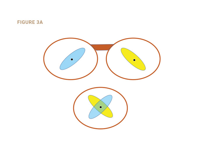
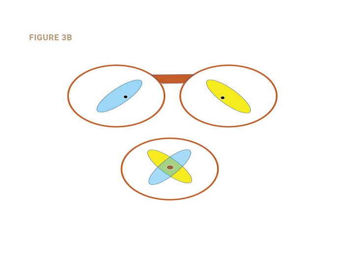
UNDERSTANDING THE SWEET SPOT
The “sweet spot” is an area surrounding the MRP of single vision and lined lenses, and the DRP of PALs. It is that area throughout which the patient does not sense any reduction in lens performance compared to the performance through the point considered. The sweet spot fluctuates due to pupil changes, viewing distance, ambient lighting and other factors possibly including the patient’s state of mind. The sweet spot should be considered a binocular phenomenon (Figs. 3a and 3b). It is obvious from Fig. 3b that if monocular sweet spots are to be used simultaneously, the size of the binocular sweet spot may be compromised by an inaccurate PD or MRP height.
ABERRATIONS OF PRIMARY CONCERN
Marginal astigmatism increases as the tilt of the lens is increased, so excessive wrap (tilt around a vertical axis) and inappropriate panto angles should be avoided. Power error increases as the line-of-sight moves further from the Optical Center (OC), so limit decentration to ≤ 3 mm (equal to or less than 3). Chromatic aberration increases as the amount of prism that the line-of-sight encounters increases. When troubleshooting, divide the prism at the lateral periphery of a lens into the prism at that meridian to find an index of peripheral chromatic aberration at that point. Values over .25 or so may relate to patient’s symptoms particularly for viewing distances of 30 feet or more.
ADAPTATION
If the patient in Fig. 2a looks up and to his left, his right line-of-sight may remain within their sweet spot (blue oval), but their left line-of-sight, since eye movements are yoked, will also move up and to his left, causing a detectable reduction in the quality of the retinal image from the left eye. It is conceivable that part of adaptation to his new lenses may be “learning” to move the head so that both lines-of-sight fall within the binocular sweet spot, or to suppress the less distinct retinal image, or to tolerate the result of fusing the now dissimilar retinal images.
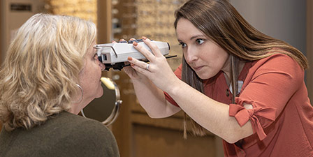
TAKING THE MEASUREMENTS
Tools for determining the monocular PDs and MRP and FC heights include PD rulers, pupillometers and various electronic devices using iPads or custom-designed hardware and software. Some auto-refractors also feature an ability to take PD measurements. Opinions vary on the efficacy of all methods.
PD measuring systems often make PD measurements relative to the separation of the anterior corneal reflexes. This ignores the fact that the anterior corneal reflex usually does not coincide with the visual axis of the eye. The monocular PD should be relative to the center of the bridge of the patient’s frame, which is not always centered just above where pupillometers tend to rest. A quick glance at how the pupillometer rests and at the patient’s nasal asymmetry is a good idea.
A PD rule is inexpensive and efficient, but if the optician’s PD differs from the patient’s PD, the measurement will be flawed. Even if the PDs are the same, a difference in pupil size or corneal diameter, or the displacement of the anterior corneal reflex from the visual axes (angle Kappa) can affect the accuracy of PD measurements.
You can validate your findings using a trial frame and two trial lenses of low cylinder power. A red lens-marking pen should be used to draw a line through the center of the lens and connecting the axis marks in the periphery. Place the lenses in the trial frame with the axes at 090. The trial frame should be fitted level with equal vertex distances. The patient then views his own face in a plano mirror mounted flat on a vertical wall. Occlude his left eye and ask him to look directly at the mirror as you adjust the right PD knob of the trial frame until he sees a wide pink stripe with the line on the trial lens centered within it extending straight through the center of his right pupil. Then move the occluder to the right eye and adjust the left PD knob as you did for the right eye. The patient must not move his head during this procedure. Turning the lenses to axes 180 OU can help identify hyper eye situations.
The sum of the two readings on the trial frame’s PD scales will be the separation of the parallel lines-of-sight. This technique is for validating your chosen method of measuring PDs. Corneal reflex pupillometers will vary due to differences in angle Kappa. With the methods utilizing iPads or cameras, there may be other factors that can raise uncertainties about PD measurements.
OCCLUSION DURING PD MEASUREMENTS
Every ECP has seen the hyperopic child with an eye that turns inward when the glasses are not being worn and which immediately straightens when the glasses are put on. Parents are usually astonished (sometimes to tears) when they see this happen. This straightening effect is due to the relationship between accommodation (contraction of the ciliary muscles that focus the eye) and the extra ocular muscles that cause the eyes to converge. This relationship is called the AC/A ratio, and it is the amount of accommodative convergence (AC) that is generated when the eyes accommodate (A) one diopter.
A hyperopic child who is not wearing corrective lenses will have a certain amount of tendency to converge his eyes for every diopter of accommodation needed to bring the retinal image into focus. If the amount of hyperopia is moderate to large there can be an excessive stimulus to converge, and one eye will turn inward when lenses are not worn. With corrective lenses, the retinal image will be clear without excessive accommodation and the eyes straighten. Hyperopia is not the only reason that eyes may not simultaneously aim at the same target. Occluding the eye not being measured when taking PDs is so quick and easy that it should be done for all patients.
Since it is awkward and impractical to take PDs with spectacle lenses in place, and since patients may exhibit an excessive turning of one eye even with the lenses in place, alternate occlusion is used to eliminate errors. When using a pupillometer, you should occlude whichever eye you are not measuring so you know that you are measuring the patient’s fixating eye. If you use a PD rule, the same technique of occluding the eye you are not measuring should be used. This occlusion technique, long taught for measuring patients with strabismus, works equally well for every binocular patient.
MRP PLACEMENT
For PAL lenses, the point at which the line-of-sight for distance seeing intersects the lens should be at the DRP for distance viewing, and it should be at the NRP for near viewing.
Is it any wonder that the accurate PDs, MRP heights and Fitting Cross heights are critical factors in creating eyewear that gives the best possible lens performance? Every ECP is aware of the importance of correctly placing these critical points so that the patient makes the best use of the lens technology for which he has paid. Correctly placing the MRPs and Fitting Crosses are among the most important ways of reducing adaptation problems and avoiding remakes.
GLOSSARY
Angle Kappa: The angle between the pupillary axis and the visual axis. The visual axis is usually nasal to the optic axis (a positive angle Kappa), but it can vary considerably. A negative angle Kappa would appear laterally to the visual axis.
Center of Rotation of the Eye: A point or series of points about the eye rotates as the angle of view changes.
Distance PD: The separation of the lines-of-sight when they are parallel as in viewing a distant object-of-regard. Sometimes called the interpupillary distance.
Limbus: The cornea is usually about 12 mm in diameter. The limbus is the juncture of the cornea and the sclera, so the distance from the center of the cornea (or pupil) to the limbus is about 6 mm.
Line-of-sight: The ray path that joins the object of regard with the point on the retina which the patient uses to achieve his best acuity. For most patients, that point would be the fovea centralis, which is packed with cone receptors to give the most well-defined analysis of the retinal image.
MRP: The MRP or Major Reference Point is the point in SV and lined lenses that gives the prescribed refractive power and prism that the patient requires for best vision. For PALs the prism, if any, is placed at the Prism Reference Point (PRP), and the prescribed refractive power is at the Distance Reference Point (DRP).
Near PD: The separation of the lines-of-sight when a nearby object-of-regard is being viewed. The separation is dependent on the distance at which it is measured. If the centers-of-rotation of both eyes were a single fixed location, their separation would equal the distance PD at all times, even when a near object was viewed. The separation of the lines-of-sight should be measured at the point they intersect the lenses during use.
Normal: When a line or light ray intersects a surface at a 90-degree angle, it is said to be normal to that surface.
Objective PD: The distance between the lines-of-sight measured by a trained observer or an instrument that makes a determination independent of the observation of the person being measured.
Pupillary Axis of the Eye: The line from the center of the pupil and normal to the pupillary plane.
Subjective PD: The distance between the lines-of-sight as determined based on observations made by the person being measured.
Vertex Distance: The distance from the apex of the cornea to the back surface of the lens. It is conventionally measured with the line-of-sight level as though looking at the horizon. In down-gaze the vertex distance increases depending on the pantoscopic tilt, the location of the DRP (for PALs) and the location of the object-of-regard. Often lined segs are decentered 1.5 mm in each eye, which is about the inset measured when the lines-of-sight are level. PAL centration charts now often show about double that amount because of the long drop from distance viewing to the NRP.
Visual Axis of the Eye: The line from the object-of-regard to the center of rotation of the eye and from there to the part of the retina the patient uses for vision (usually the center of the fovea). Off-fovea points are often used in cases of macular disease or scarring.
Contributing editor Palmer R. Cook, OD, is an optometric educator and optical dispensing expert.