
By Barry Santini
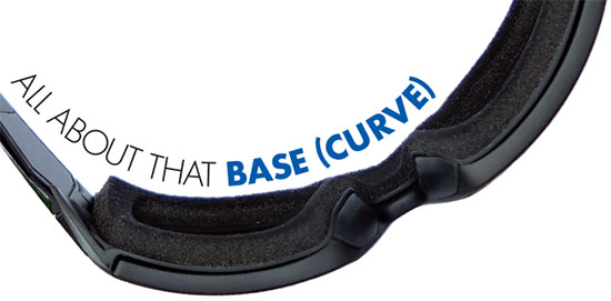
Probably no topic is arguably more confusing, misunderstood or under-appreciated than how the choice of lens base curve can impact the optics, fit and cosmetics of a new pair of prescription glasses. For a long time it’s been far too convenient to target one of the above three, make it your top priority and dismiss the other two. But by doing so, you are almost always creating significant compromises with the others.
Today, with the availability of advanced free-form lens design, accepting a compromise is no longer a legitimate choice. Therefore, the challenge facing eyecare professionals today is to learn how to achieve the best balance between optics, cosmetics and fit for every patient and every pair of eyeglasses. To fully acquire this skill set, ECPs need to understand how the human eye evolved to see the world. Second, they must also familiarize themselves with the history and fundamentals of best form/corrected curve theory. Finally, ECPs need to master how frame design, construction and fit all interact in a recipe for a pair of visually, functionally and cosmetically superlative eyewear.
HOW WE SEE
The human eye evolved from humble beginnings. Starting as a simple light-sensing device to help regulate diurnal activity, it developed into a direction-sensing organ featuring a symmetrical structure not wholly different in design from a wide-angle camera lens. As the crystalline lens evolved, it transitioned from being primarily a light-gathering structure designed to maximize gathering photons to one where its imaging properties help spark the development of the fovea, a region of higher acuity. But the fovea covers only about one degree in the eye’s field of view, and so ocular muscles subsequently developed to quickly point this small but high acuity area where our attention needed it most.
The human eye is therefore a combination of wide angle camera optimized for sensing motion to help make food, fight or flight decisions, and a high resolution camera designed for in-depth, detailed target assessment. When evaluating an object of interest, the eyes perform saccades—rapid push-pull movements—to place the foveal region in the optimal position to scan intended target. Even during fixation, the human eye does not rest, engaging instead index mini-movements of 0.5 degree and 1 second duration referred to as micro saccades. These smaller scale excursions help prevent fading of our visual precept, which maximizes the persistence of vision.
The eye’s dual camera nature also helps explain the dual nature of our visual perception: We evolved to favor the importance of having sharp central vision combined with motion-sensitive wide-angle side vision wherein the eye rotates its fovea to linger, scan and evaluate a target of interest in the periphery.
THE CONE OF VISUAL ATTENTION
Although the eye’s total field of view—central plus peripheral—stretches to over a 160 degrees, the sharpest parts of the eye, the fovea and the macula, cover only a field of view of 0.5 to 2.0 degrees and 15 to 18 degrees, respectively. As the eye rotates off the facial plane axis to scan objects of interest with the fovea, the brain integrates this information into a bigger picture called the cone of visual attention. This cone subtends approximately a 50 to 55 degree wide field of view and is sometimes referred to in photography as a normal perspective. But the eye also resists rotating beyond about a 15 degree angle to scan an object without an accompanying head movement to re-center. This means we have a total primary field of view of 30 degrees in which the eye’s gaze routinely travels, nestled within a larger normal perspective totaling a 50 to 55 degree field of view.
Combining the eye’s dual design nature with how it samples and integrates information to form our perceptual cone of attention, we can begin to appreciate why the challenge of expanding the area of sharp vision was so compelling to researchers over 200 years ago.

THE BASICS OF BASE CURVE
The frustrating experience of looking through lenses with narrow fields of view is not unfamiliar to consumers today. Having to make frequent head movements in order to see peripheral objects clearly is innately uncomfortable, and you need look no further than the experience of first-time progressive wearers to understand and appreciate their adaptation issues. Perhaps nothing is more revealing of how desensitized ECPs may have become to the importance of having a wide and sharp field of view than how reflexively they respond to peripheral vision complaints with “Don’t worry, you’ll get used to it.”
But to a lens researcher in the early 1800s named Henry Wollaston, the whole idea of tolerating the poor peripheral vision of the flat-base eyeglass lenses of the day was unacceptable. What Wollaston discovered was that by “bending” a lens into a meniscus-tear form, the area of sharp vision noticeably increased from the restricted 5 mm area/10 degree angle common to flat form lenses. Wollaston went on to apply his steeper meniscus form to lenses in the newly emerging technology of photography. His curved photographic lens became known as the “Wollaston Landscape Lens,” acknowledging its superiority for filming the wide panoramas of landscapes. It eventually became standard equipment in the toolbox of a 19th century photographer’s arsenal of lenses. Meanwhile, recognition and adoption of Wollaston’s meniscus lens form for eyeglasses was overshadowed by interest in Thomas Young’s discovery of astigmatism. Interest in Wollaston’s improved curved-lens form would lie fallow for almost 100 years, until it was rediscovered by a Parisienne oculist named Ostwalt in the late 1890s.
But Ostwalt found Wollaston’s lens designs too steep to be practical to manufacture and glaze, and began to use mathematics to help design a series of improved field of view lenses featuring flatter curves than Wollaston’s. By using mathematics, Ostwalt helped transition lens design from its 200 year legacy of empirical art to one based on a solid science, creating lenses that delivered both sharp central and peripheral vision.
The first such series of lenses created by precise ray tracing were done by Dr. Moritz von Rohr of the firm of Carl Zeiss. Dr. von Rohr designed his new Punktal lenses to deliver pin-point sharpness across a 60 degree field of view by eliminating the acuity degrading error of off-axis astigmatism. Why did Von Rohr choose 60 degrees? Because he wanted to more than cover the eye’s full cone of attention, thereby delivering absolutely top performance for Punktal’s premium asking price. Wearers would no longer have to uncomfortably turn their head to point their lens’ sharper central region toward what they wanted to see. But Punktal (for pin-point) series lenses required each correction to use its own specific radii for the front and rear surfaces. Punktal lenses cost about 10 times more than the common lenses of the day.
BIRTH OF CORRECTED CURVE
To overcome Punktal’s high cost and long fabrication times, lens designers Tyllier at American Optical and Rayton at Bausch & Lomb began to explore how to create a more economical way to produce series of corrected curve lenses using three new approaches:
1. Grouping nearby lens powers together to make them on a single curve, thereby reducing inventory and tooling.
2. Prioritized the area targeted for pin-point correction to a 15 degree angle/30 degree FOV. This was supported by the recognition that this matched the general limit of the eye’s rotational excursion before accompanying head movement would be initiated. (Note: The exception here to the 15 degree rule is found during reading, where the eye rotates down and across the page between 30 and 60 degrees, respectively.)
3. Allowing a certain amount of power (0.24D) or astigmatism error (0.12D) in the peripheral region beyond the 15-plus degree area subtended the macula. These limits were seen as reasonable because of the eye’s ability to accommodate small power errors and that accepted exam room precision of this era was 0.12D.
Before the advent of precise mathematical tracing, the optimal approach for obtaining “best form,” aka best peripheral performance lenses, was found empirically with an ocular curve of 6 diopters. This 6D rule of thumb worked well because it accomplished two things:
1. Kept the front curves steeper in profile, which reduced the obliquely of peripheral gaze angles, thereby reducing tilt and oblique astigmatism.
2. Made the image shell formed by this 6 ‘base curve’ meniscus lens form—base curve equaled rear curve because toric prescriptions placed the cylindrical correction on the front side—approximated the curved focal plane of the eye’s retina and the arc of the fovea-macula, the far point sphere—when the eye moved about its center of rotation.
LIMITATIONS OF CORRECTED CURVE
Corrective curve lens design required accepting trade-offs from the zero-astigmatism goal of the Zeiss Punktal lenses in order to reduce the number of curves and shop tools required:
1. Stronger Cylinder Powers were not fully included in the target optimization.
2. Best performance is only realized when the corrective lens was placed orthogonally in front of the eye, i.e., the lens’ optical axis passed through the eye’s center of rotation. This aligned the lens properly for all gaze angles of the eye.
3. Lenses were assumed to fit at a normalized distance. Designers assumed a fitted vertex distance of approximately 14 mm, a value arrived at after measuring hundreds of eyeglass fittings and averaging the data to a mean value.
4. Finally, in order to ensure a lens’ image shell aligned properly with the eye’s far point sphere, a required condition for reducing any focus or power errors, the eye’s center of rotation was assumed to be typically 13.0 mm behind the cornea. This brought the assumed lens-to-CR distance to a total of 27 mm. In retrospect, we see that this assumed 27 mm CR distance was perhaps over simplified, as it did not consider axial length influences such as type of ametropia, axial length variations or individual preferences (lash clearance, sinus sensitivities or other personal cosmetic requirements).
THE STEEP PRICE OF STEEPER
Wollaston, von Rohr and other best form adherents all found steeper curves better when it came to the form of lenses offering good peripheral clarity. But steeper curves make steeper demands on thickness, weight, glazing and create unwanted changes in magnification. Why? Because the greater sag of steeper curves results in greater thickness and bulge, also known as plate height.
Today, one way to reduce thickness is a higher index of refraction material. By using higher index’s greater light bending power, flatter curves can now be used. This reduces plate height and helps overcome problems of increased thickness, weight, magnification and glazing difficulty.
Except for one problem: Greater light bending power at the periphery means the obliquity of off-axis light bundles are refracted even more, increasing the effective tilt of the lens surface and thereby increasing peripheral astigmatism. Therefore putting higher index materials must be placed on steeper base curves, not flatter, in order to maintain compliance with corrected curve theory. This is where using aspheric surfaces on higher index lenses became the norm: By using surface astigmatism to counteract peripheral off-axis astigmatism, aspheric surfaces reduce the steeper curves needed for maintaining peripheral clarity, thereby reducing bulge/plate height, thickness, weight and glazing difficulty, as well as the unwanted magnification increase caused by steeper front curves.
FITTING THE FRAME WITH FREE-FORM
When glazing a frame, the ideal is to have the lens base curve match the frame’s bevel curve. This is terrific if your goal is to make the Rx lens appear to fit like a plano lens in sunglasses.
Unfortunately, this approach places all the additional thickness of a prescription lens behind the frame, where it can interfere with nosepads and their adjustment, temple closure and even press on the end pieces, thereby impacting frame wrap angle, optics and fit. An alternate approach is to try to straddle the extra thickness of a prescription lens with the frame eye wire, minimizing the amount of lens extension beyond the eye wire. But sometimes a particular corrected curve or aspheric lens will not have base curve suitable for obtaining the desired bevel placement. So what can an optician use to best balance lens thickness, curve, optics and glazing to deliver the best overall pair of eyewear?
STEALING BASES
By using a digitally optimized, true free-form lens design, eyecare professionals finally have a tool that allows less compromise between optics, cosmetics and fit when creating the best pair of wear. Instead of being restricted to using a traditionally-manufactured lens design’s base curve, advanced free-form lenses can offer the ability to deviate from the designer’s target base curve up to 2 diopters in either direction. For Rxs less than 3 diopters total power, stealing a nearby base curve up to 3 diopters from the original design’s default may be possible without additional peripheral compromise. Of course, the exact curve available may depend on the index of refraction you select. It’s a true balancing act, worthy of bestowing artisan status to those opticians who really learn how to do it well.
MATCH BASE CURVE?
So what should an optician do when they see a prescriber write “match base curve” on a new Rx? Ignore it? No... understand it. Wrapped up in the phrase “match base curve” is a window to a previous time when lens design and fitting lacked the robust tools we have access to today. Of all the parameters impacting wearer adaptation and comfort, one of the few besides the Rx under the prescriber’s control are the changes in magnification and perspective a patient experienced from changes in base curve. However, free-form design now allows the optician to make the best base curve choice for the glasses at hand. And since the optician is ultimately the one responsible for satisfactory fulfillment of the Rx, they alone should be allowed the option of selecting the base curve which strikes the best balance in the eyewear’s optics, fit and cosmetics. May all your base curves be chosen wisely.
ADVANCED BASE CURVE CONSIDERATIONS
Most of corrected curve theory is technical but accessible to any eyecare professional. Below are a few of the more advanced concepts that will help to achieve a more complete understanding of the science of base curves.
OPTICS AS A SHELL GAME
For an ametropic eye, the object point from which light rays will focus on the retina is called the far point. As the eye rotates around its CR, the sum of these far points describe a spherical, shell-like surface called the far point sphere. A corrective lens that focuses light as if it were focusing on the far point sphere produces a sphere-like focal surface called its image shell. The ultimate goal of a perfectly-designed corrective lens is to have the lens' image shell align exactly with the far point sphere of the uncorrected eye. If a lens is not completely correcting off-axis astigmatism, it actually produces two focal plane image shells, which can be placed in various positions relative to a particular far point sphere by the designer.
When a lens completely corrects for off-axis astigmatism, its design is said to be Petzval compliant, after a lens engineer who first created this design. In the original Punktal lens, peripheral astigmatism was completely corrected for a 30 degree field angle. The resultant Petzval image shell, however, wasn't necessarily fully aligned with the eye's far point sphere, resulting in a minor but tolerable amount of residual power error. Over the years, lens designers have assigned proprietary merit weighting when correcting and balancing astigmatism and power error over a specific gaze angle. This helped determine exactly how the lens' image shell would align with the eye's far point sphere. Unfortunately, perfection is elusive and is dependent on how the lens is fitted in front of the eye by the optician, with respect both to its tilt and its distance relative to the eye's center of rotation.
AN UMBRELLA VIEW OF LENS PLACEMENT
It is helpful to imagine a lens' image shell to that of an open umbrella, with the umbrella's handle representing the lens' design pole. With this in mind, the goal of the optician becomes twofold:
1. Place the pole of the umbrella so it intersects the eye's center of rotation. This will make the umbrella's canopy (image shell) parallel to the eye's far point sphere as uniformly as possible throughout all gaze angles.
2. Longitudinally position the umbrella's canopy so its shell, i.e., the lens' image shell, is coincident with the eye's far point sphere. Deviations here result in power errors opticians incompletely address when they perform a vertex distance compensation. Why incompletely? Because vertex compensations only address variations in lens to cornea distance, leaving unaddressed respect the eye's center of rotation distance behind the cornea.
A KNOW UNKNOWN: THE EYE'S CENTER OF ROTATION
From our discussion above, it's clear that knowing the location of an eye's center of rotation is an important factor for optimal alignment of the lens image shell to the eye's far point sphere. But how do we go about discovering this location? Some newer digital centration devices, such as Essilor's Visioffice, have metrology components that assess the CR position in a generalized way. In addition, Essilor research discovered that the eye's axial length and CR position are associated with certain racial anatomical considerations. Asians tend to have longer axial length and more rearward CRs, while those of Indian ancestry have shorter axial distances and decreased CR distances. All these comparatives are made with respect to a traditionally assumed CR distance of 27 mm.
But the distance of a lens relative to the center of rotation is also impacted by how far from the cornea the lens is fitted. Here, wearer personal fitting preferences include lash and brow clearance, sinus sensitivity, bridge anatomy and overall frame fitting preferences. And remember: Gravity always works to pull a lens down and away from the eye, increasing vertex distance.
POSITIONING THE POLE
In fitting a conventional corrected curve or aspheric lens, the optician must ensure the lens' design pole—the handle in our umbrella analogyーintersects the eye's center of rotation. This has been traditionally accomplished by employing Martin's Rule of Tilt, whereby every degree of pantoscopic tilt required ticketing the lens' optical axis to compensate. Since the optical axis, by definition, passes perpendicularly through the optical center, or OC, simply moving the OC downward 0.5 mm for every degree of pantoscopic tilt will bring the lens' image shell in proper rotational alignment to the eye's far point sphere. Martin's Rule assumes a cornea vertex distance value of 13.75 mm, so larger measured deviations in vertex will require some recalculation of this rule of thumb.
FREE-FORM AND POSITION OF WEAR
If you are not routinely measuring vertex distance along with the other position of wear factors including pantoscopic tilt and frame wrap angle, it should now be clear that you should start. Although most free-form designs can use default fitting values gleaned from averaging data across thousands of fits, only the individual values found from the wearer at hand matter to the expert optician. Using advanced free-form designs, what is really going on when you input personalized fitting values is that the lens design engine makes real-time computations using dynamic merit weighting to arrive at a free-form lens surface that best aligns the image shell with that of the eye. This compensation is adjusted for many factors, including lens size, shape and ED. These last three factors, along with vertex distance, help to map the eye's cone of attention and rotating angles onto the surface of the lens, impacting the surface adjustments made for correcting the most significant aberrations.
MARKED CURVE VS. TRUE BASE CURVE
One hundred years ago, at the dawn of scientific lens design, only one material was used for lenses: That material was crown glass, with an index of refraction 1.53. This is what shop tools and gauges have been calibrated to when the surface dioptric power is marked. But the introduction of higher index materials, with their greater light bending power, required labs to remark their lens blanks to reflect the increased light bending effect. This is done so that curve calculations will produce lenses with the desired power. Today, we live in an era of lenses having a marked dioptric power for their base curve that differs from that lens' true surface curve, which is measured with a lens clock calibrated to an index of 1.53. The important curve for opticians to remember here is the true curve, which is what they need to know when choosing the proper base curve for fit-to-frame considerations.
THE MAGNIFYING EFFECT OF BASE CURVE
The radius of curvature of a lens' front curve, aka its base curve, along with the lens' thickness, help to determine its overall cosmetic and image magnifying on the eye. The steeper the front/base curve and the greater the lens thickness, the greater the magnifying effect. The combined effect of front curve and thickness is called a lens' shape factor, and it can play an influential role in affecting a wearer's comfort and perceptual adaptation to a new Rx.
MYOPIA, ASTIGMATISM AND THE PETZVAL CONDITION
As lens engineers achieved success in correcting the peripheral astigmatism for large gaze angles of up to 30 degrees, they noted the resulting Petzval image shell was routinely located to the hyperopic side of the eye's image shell. This was considered acceptable, since the eye can compensate for small amounts of hyperopic defocus through accommodation. However, if the Petzval surface/shell was found on the myopic side of focus, the eye couldn't compensate by refocusing the image through accommodation, and designers avoided this approach for this reason.
But there's a potentially latent problem here. Today, vision experts have theorized that hyperopic defocus in the peripheral retina area may be a suspect in the growing epidemic of myopic progression seen around the world. Put another way, the best designed lenses—the ones with the sharpest correction for peripheral clarity—may be an unwitting accomplice to the significant increases seen in myopic progression.
THE GORILLA IN THE PERIPHERY: ABBE
Despite what corrected curve, aspheric and today's advanced free-form designs can deliver in superior peripheral clarity, the one aberration that cannot be overcome through lens design is chromatic error. This is strictly dependent on the dispersive properties of the lens substrate and is described by an inverse quotient known as the Abbe value of a lens material. The lower the Abbe, the greater amount that colors are dispersed and the greater the potential impact on acuity. The total effect of Abbe on peripheral acuity is a combination of the total diopter power, fixation distance from the optical center and the Abbe value of the material. Because color error increases as you look away from the OC, some opticians have chosen to prioritize OC placement over all other considerations.
But they have chosen unwisely. By prioritizing OC placement in front of the pupil, without regard for pantoscopic tilt or vertex distance, they have chosen to misalign the lens' image shell with the eye's far point sphere, further compounding Abbe's potential impact on peripheral acuity. The best approach for prioritizing peripheral clarity is to:
1. Ensure ideal image shell position through proper lens alignment.
2. Select the most favorable Abbe value material yielding the thickness desired.
3. Tweak the base curve choice using a fully POW compensated lens design.
4. Fit a properly chosen frame to deliver the best acuity across the entire lens surface.
Understanding why prioritizing OC placement in front of the pupil is incorrect will hopefully lead to the end of using the phrase "taking an OC height," because what you're really after is taking a pupil height. It's what you do with that height and the OC that separates the optician masters from the apprentices.
THE ENGIMA OF ENIGMA
In the early 2000s, lens designer Michael Morris of SOLA Optical revisited the Wollaston branch of steeper-profile corrective curve lenses with an eye toward using moldable polycarbonate material to create a unique lens of superior peripheral vision. The result was the Enigma/Contour Optics lenses, which featured correction for peripheral astigmatism, power error and unwanted magnification, along with reduced off-axis prism effect. The main design principle was the Enigma's base curve of 16 diopters which, when placed at a vertex distance of 14 mm from the cornea, allowed the front curve's radius to pass through the eye's center of rotation. In effect, every ray off-axis had a normal incidence to the lens surface wherever the eye looked. The result: exceptionally sharp, wide fields of view from a lens of smaller size. In addition to improved peripheral eye protection, Engima lenses also reduced the amount of observed chromatic aberration through the same reduction in oblique incidence.
L&T contributing editor Barry Santini is a New York State-licensed optician based in Seaford, N.Y.